EN
EN
 ES
ES ID
ID CN
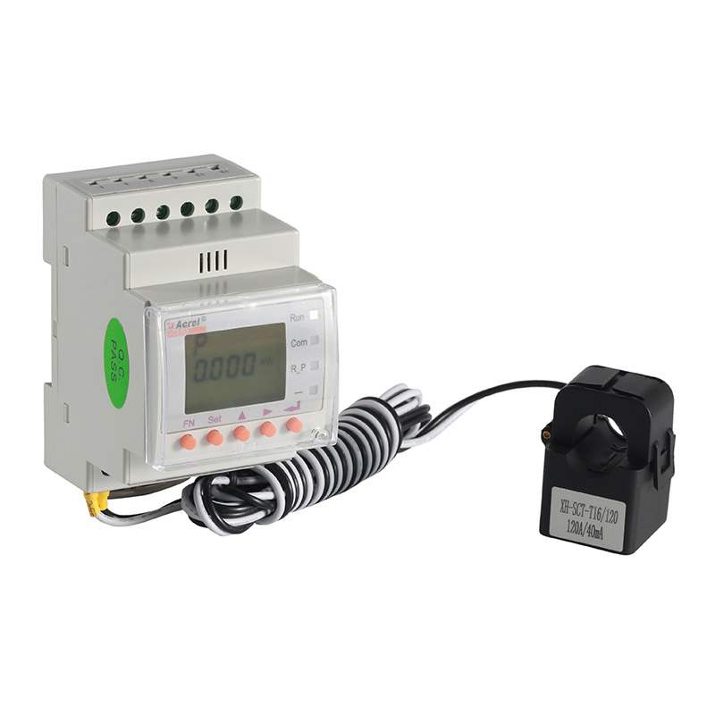
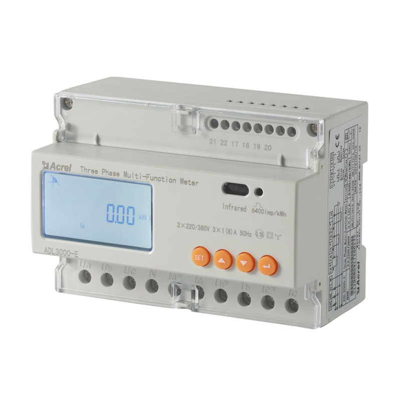
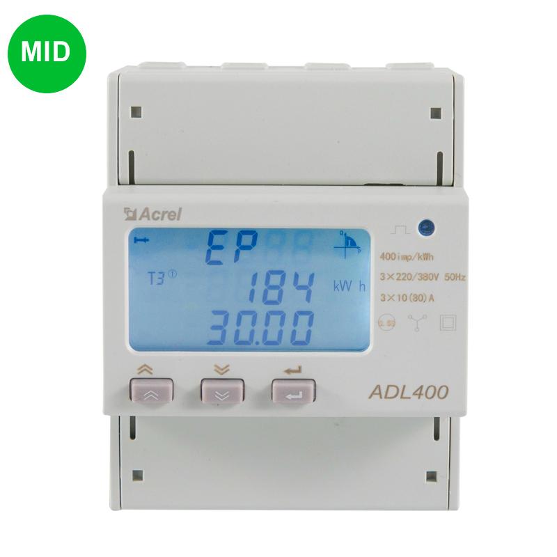
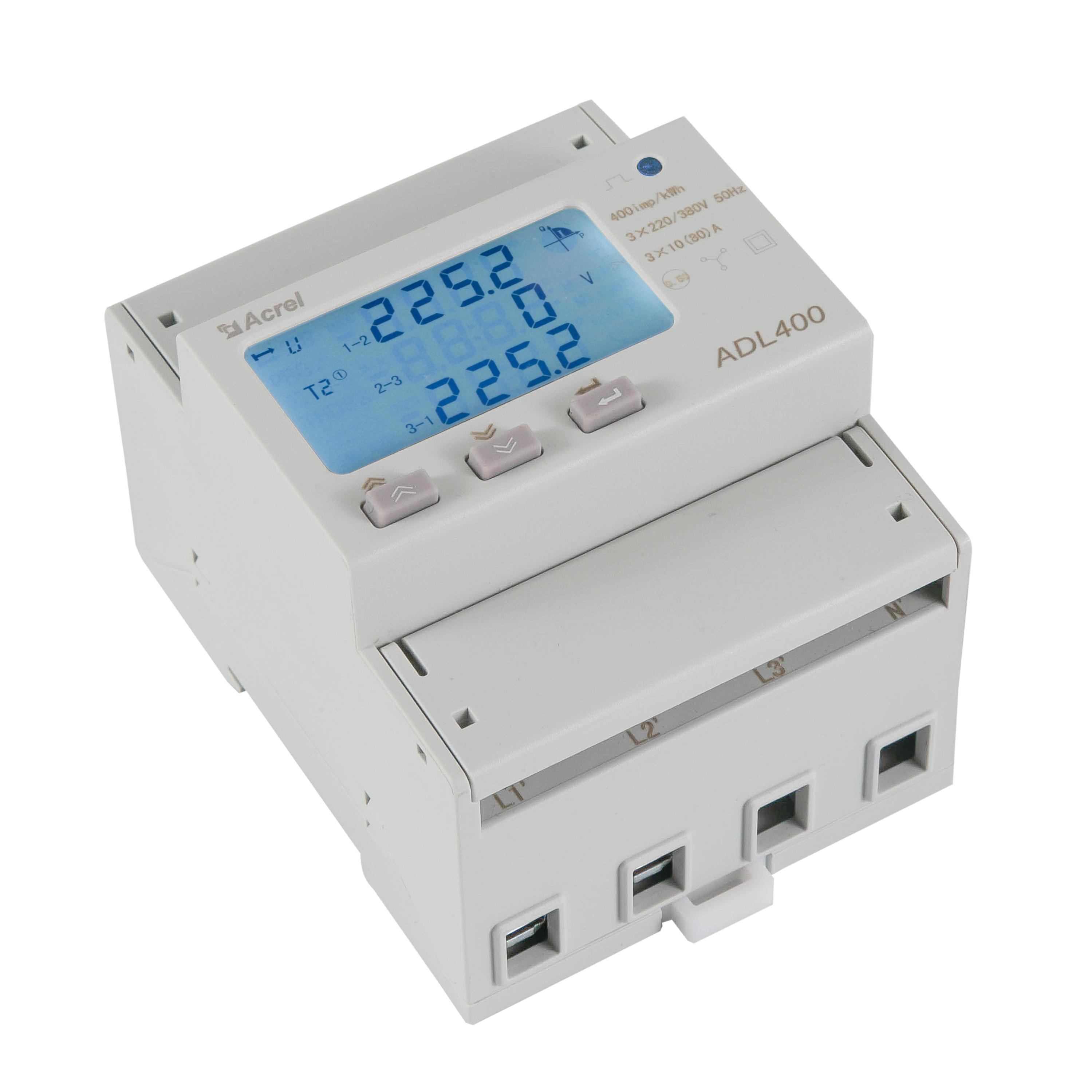
CNMedidor de energía de carril DIN trifásico ADL400
● Rated Current: 1 (6) A, 10 (80) A
● Rated Voltage: AC220V/380V, AC230V/400V
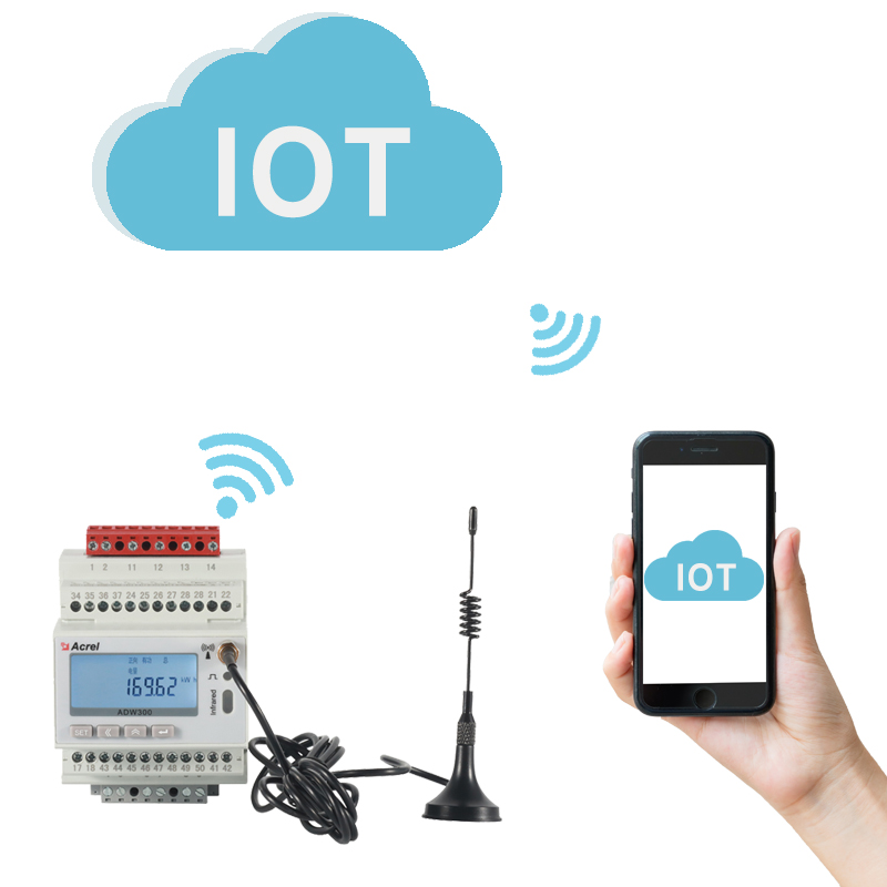
● RS485(MODBUS-RTU) Communication
● 12 digits LCD Display; 35mm DIN Rail Installation
● 2~31st Harmonic Measurement
● kWh Class 0.5S
- Resumen
- Parámetro
- Certificados
- Preguntas y respuestas del cliente
- Contáctenos
ADL400 din rail energy meter adopts DIN35mm din rail installation with LCD display,it can measure electric parameters and has energy pulse output, RS485 communication,which has the advantages of small size, high precision, good reliability and convenient installation.

① Voltage Enter-wire
② Marca
③ Panel
④ Up Button
⑤ Down Button
⑥ Auxiliary function
⑦ Pulse Output
⑧ Model
⑨ Set Button
⑩ CT Enter-wire
clave


Pantalla

Alambrado

| proyecto | parámetro de rendimiento | ||
| Especificaciones | 3 fases 3 hilos, 3 fases 4 hilos | ||
| Medición | Voltaje | Reference voltage | 3×100V、 3×380V、3×57.7/100V、 3×220/380V |
| Consumo | <10 VA (monofásico) | ||
| Impedancia | > 2 MΩ | ||
| Clase de precisión | Error±0.2% | ||
| Disponible | Corriente de entrada | 3×1(6)A, 3×10(80)A | |
| Consumo | <1VA Single phase rated current | ||
| Clase de precisión | Error±0.2% | ||
| Energia | Activa, reactiva, potencia aparente, error±0.5℅ | ||
| Frecuencia | 45~65Hz,Error±0.2% | ||
| Medida | Energía | Active energy(Accuracy class: 0.5) reactive energy(Accuracy class 2) | |
| Reloj | ≤0.5s / d | ||
| Digit signal | Salida de pulso de energía | 1 active photocoupler output | |
| pulso | Ancho de pulso | 80±20ms | |
| Constante de pulso | 400imp/kWh,10000imp/kWh(Correspond with the basic current) | ||
| la comunicación | Interface and communication protocol | RS485口:Modbus RTURS485:Modbus RTU | |
| Rango de dirección de comunicación | Modbus RTU: 1~ 247; | ||
| Velocidad de transmisión | 1200bps ~ 19200bps | ||
| entorno | temperatura de trabajo | -25 ℃ ~ + 55 ℃ | |
| Humedad relativa | ≤95℅(Sin condensación) | ||
-
Descargar
Manual
Preguntas y respuestas del cliente
-
Respuesta
Switch the meter display to the power (active power P, power factor λ) interface, and check whether the power display is negative or not. And whether the power factor is between 0.9-0.95, and then check whether the incoming and outgoing wires of the current signal wire are connected reversely (that is, the current The incoming wire must be the same as the incoming wire end of the instrument) and consistent with the wiring diagram on the instrument.
casarse 31 de agosto de 2022
-
Respuesta
1. The voltage value between the communication output A and B of the measuring instrument should be between +(4.4-4.5)V; 2. Check whether the communication wiring method is correctly wired in accordance with the wiring diagram requirements (that is, the communication terminal A/B of the corresponding to communication serial port A/B);
casarse 31 de agosto de 2022